Illustrations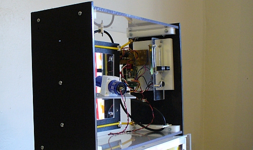 Figure 1. Vibrating mirror project - first prototype.
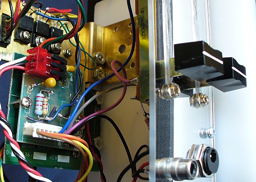 Figure 2. Detail showing electronics sled.
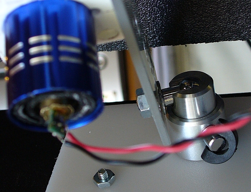 Figure 3. Closeup of laser sled (rotated).
 Figure 4. Image obtained when motor speeds are set about 2x apart.
 Figure 5. The projected image will normally
 rotateat the beat frequency. |
Vibrating Mirror ProjectIntroduction
This is my first attempt at a more Vibrators jiggle a mirror suspended in the frame by bungie cords. A laser positioned in front of the mirror sends a beam to its surface which is then reflected onto a wall on the opposite side of the room. The pattern on the wall shows the effect of the two vibrators on the motion of the mirror's surface.
These are technically known as Sub-assembliesThere are four main sub-assemblies:
mirror plasticand is mounted on a plastic holder. The motors are mounted on the other side of this holder (could have been on mirror side) using metal straps. They are mounted at the edge, with a 90 degree angular separation.
The term
The electronics sled contains the power source for the laser and the motors.
This is a Materials
All the sheet plastic is from the
The vibrating motors are from a The laser is from a Radio Shack laser level. Its housing is a cheap LED flashlight housing.
The electronics and cabling is all from The pivot mount on the laser sled is from a mini-tripod sold by Radio Shack. I did not machine it myself! PatternsThe more interesting pattern I could get with this setup is the 2:1 pattern. However, other patterns are available by tweaking the controls. When both motors run full on you get a 1:1 pattern that is usually a narrow oval. But by playing around with the controls, you can get a wider oval. When one motor is totally off you also usually get a narrow oval. The stiffness of the suspension system and the strength of the motors will determine how much the mirror vibrates. The electronics' ability to throttle down a motor without it stopping will determine how far beyond the 2:1 speed difference you can get. The addition of a third motor would be possible, but I haven't tested that yet. The laser color did not photograph well at all. These photos only look red because I enhanced them by taking out most of the blue. I'm not sure if that is common with lasers. They are a narrow-bandwidth coherent light source, and that makes them behave in somewhat peculiar ways. You must take precautions around lasers to not look into them. Doing so has been known to cause eye damage.
The patterns are normally quite dynamic.
Because the motors are electrically separate,
they don't stay at a totally constant relative speed.
That slow drift is reflected by a rotating effect in the pattern.
In radio and piano tuning, that difference is the |